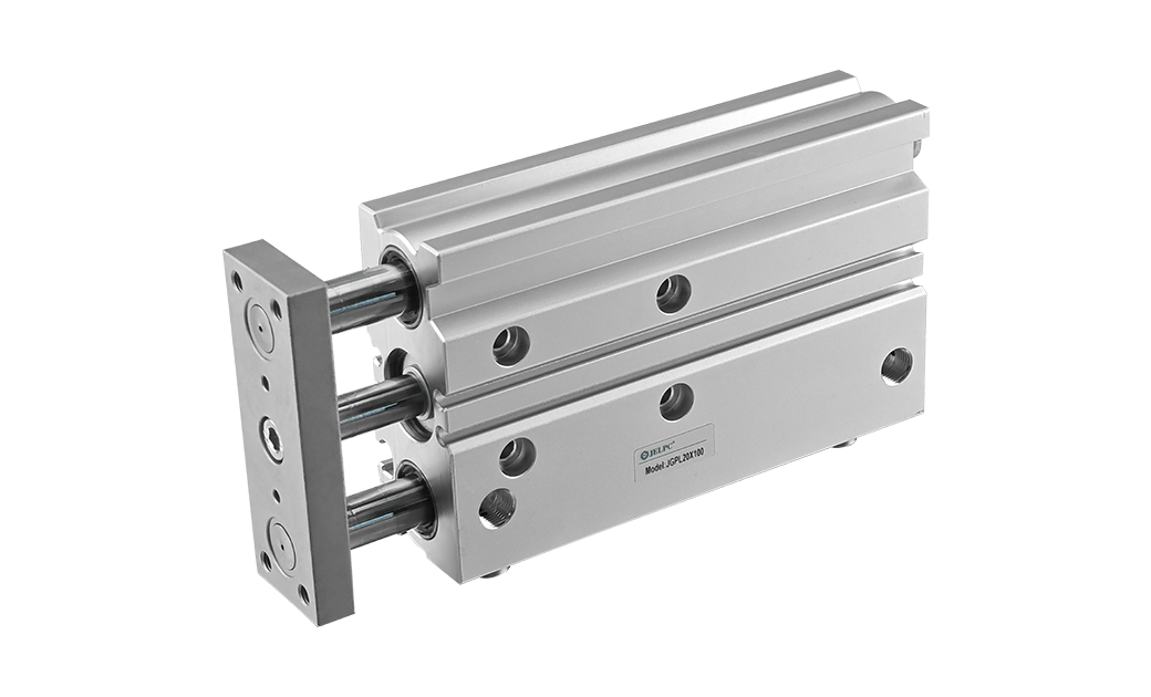
The compressed air is used to push the multiple sets of combined pneumatic pistons in the actuator to move, and the force is transmitted to the crossbeam and the characteristics of the inner curve track to drive the hollow spindle to rotate. The compressed air disc is sent to each cylinder, and the air inlet and outlet positions are changed to change the spindle rotation. Direction, according to the requirements of the load (valve) rotation torque, the number of cylinder combinations can be adjusted to drive the load (valve) to work.
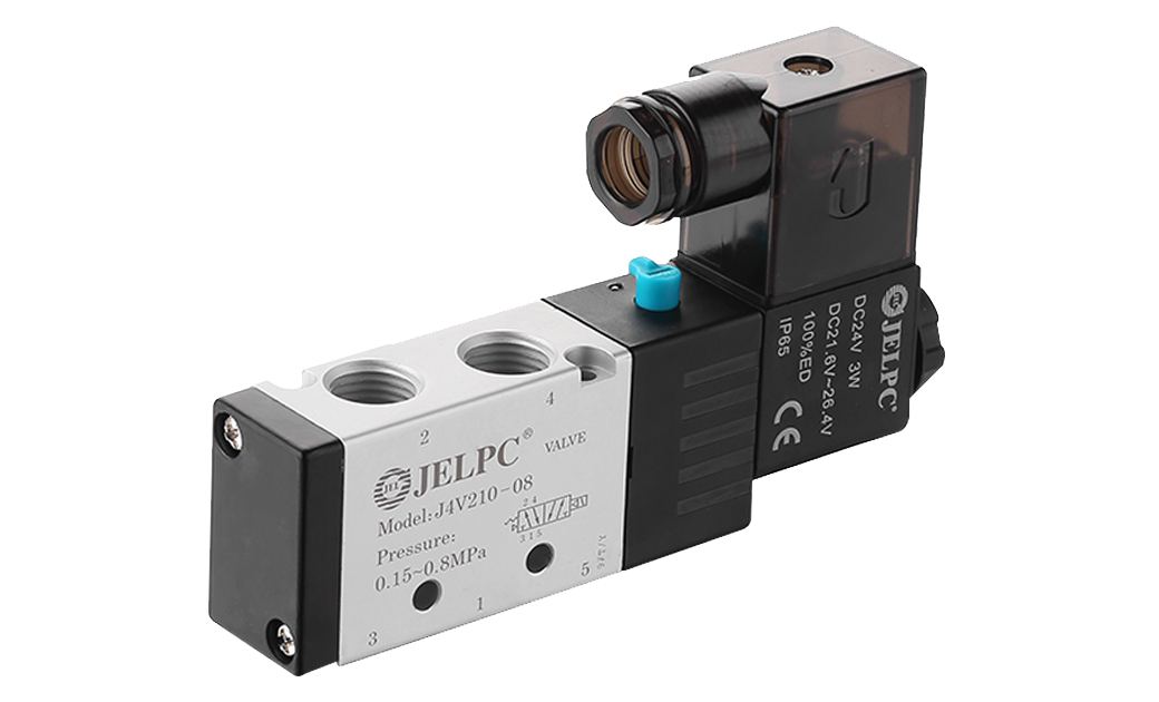
The two-position five-way solenoid valve is usually used in conjunction with a double-acting pneumatic actuator. The two-position is controllable in two positions: on-off. The five-way valve has five channels for ventilation, of which one is connected to the air source, and two are connected to the double The inlet and outlet ports of the outer chamber of the acting cylinder are connected, and the two are connected with the inlet and outlet ports of the inner chamber. The specific working principle can refer to the working principle of the double-acting pneumatic actuator. Due to the increasing number of control methods and means, there are many methods used to control pneumatic actuators in actual industrial life and industrial control. The following are commonly used.
Smart display
The intelligent display is an instrument used to monitor the working state of the valve and control the valve's execution period. It monitors the working state of the valve through two position sensors, judges whether the valve is in the open or closed state, and records the number of valve switches through programming , And there are two 4-20mA outputs corresponding to the valve opening and two-leg normally open and normally closed output contacts. Through these output signals, the opening and closing action of the valve is controlled.
Control System
The application of PLC in the control system is more and more extensive. Since this solution is developed on OMRON's PLC, it is introduced with OMRON's PLC.
Hardware composition: 1 computer, 1 set of PLC (including CPU, I/O module, ID212, OC224, AD003 module), 2 relays, 2 solenoid valves, 1 pneumatic valve actuator.
Common enquiries
1. The specifications and types of pneumatic valves produced should meet the requirements of the pipeline design documents.
2. The model of pneumatic valve should be marked with the national standard number requirement. If it is a corporate standard, the relevant description of the model should be indicated.
3. The working pressure of the pneumatic valve is required to be greater than or equal to the working pressure of the pipeline. The working pressure that the valve can withstand should be greater than the actual working pressure of the pipeline without affecting the price; any side of the pneumatic valve should be able to withstand 1.1 times when the valve is closed The valve pressure value does not leak; the valve body should be able to withstand twice the valve pressure when the valve is open.
4. Pneumatic valve manufacturing standards should state the national standard number on which it is based. If it is a corporate standard, the purchase contract should include corporate documents.
No 1.Xingjia Road, Pneumatic industrial park, Xikou,Ningbo, Zhejiang Zip code 315502
+86-574-88869818
+86-574-88869826
+86-574-88869817
+86-574-88869816
+86-574-88869833
royshan@jelpc.com

Copyright Ningbo Jiaerling Pneumatic Machinery Co.,Ltd.. All Rights Reserved. 
China Proportional Valves Manufacturers
 简体中文
简体中文 English
 日本語
日本語 한국어
한국어 Deutsch