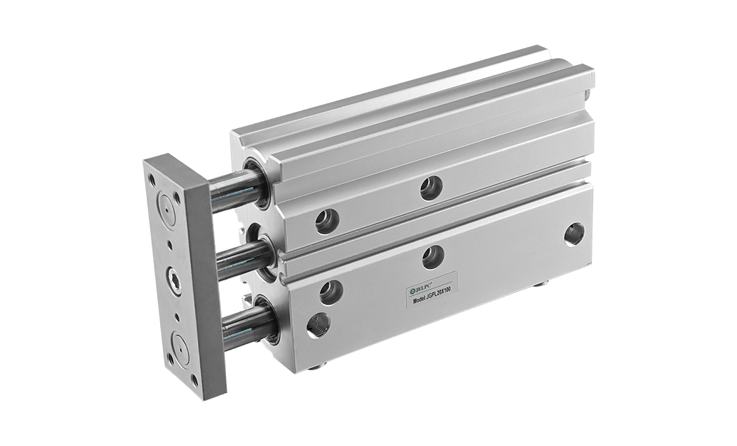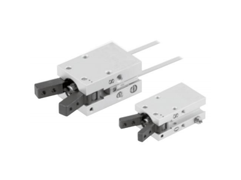
Features:
* Multi-sided free installation, compact structure design, space saving.
* Built-in flow regulator.
* Built-in magnetic ring, can install auto switch on multiple sides.
* High positioning accuracy.
Specification
| Bore Size(mm) | 10 | 16 | 20 | 25 |
| Working Medium | Air | |||
| Operation | Double acting | |||
| Min. Operating Pressure | 0.15MPa | |||
| Max. Operating Pressure | 0.7MPa | |||
| Ambient And Fluid Temperature | 10~60℃ (with no condensation) | |||
| Max.Operating Frequency | 180(C.P.M) | |||
| Sensor | JEL-07D | |||
| "Grease | No need | |||
| Cushion | Rubber cushion on both ends | |||
| Piping Size | M3X0.5 | M5X0.8 | ||
Ordering Code
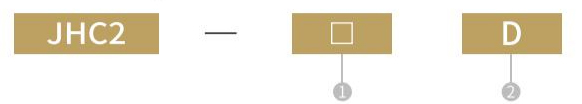
| ①Bore Size | ②Double Acting |
| 10 | - |
| 16 | |
| 20 | |
| 25 |
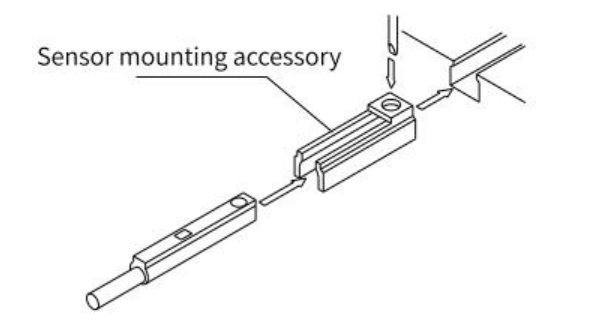
① Insert the sensor mounting accessoryinto the mounting groove on the cylinder as shown in the picture, and generally set the position of the sensor
② Insert the sensor in the mounting groove of the mounting accessory
③ After the detection position is confirmed, fix the sensor with the stopscrew (M2.5) attached to the sensor
④ The change of the detection position is carriedout according to the step②
[Note] Use the horologic driver with a grip diameter of 5-6mm when fastening the mounting screws. And the tightening moment is about 0.05~0.1 N· m, with a rough tightening feeling, then turn it 90°.
Sensor Mounting Accessory and model
| Sensor Model | Sensor Mounting Accessory Model |
| JEL-07D/JEL-07N | BMG2-012 |
Fixing Method of Sensor
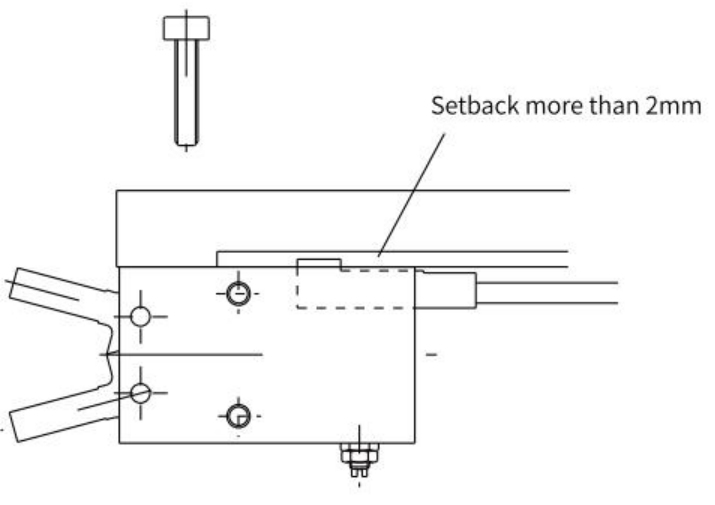
Note for using mounting accessory
When the sensor is used on the side of the mounting surface as shown in the above figure, due to the protrusion of the sensor mounting accessory from the end face, so the mounting plate should be designed with a setback of more than 2mm.
Gripping Forces Correspond To Different Grippingpoints
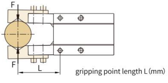
Theoretical Gripping Moment
| 10 | 16 | 20 | 25 | ||
| Theoretical Gripping Moment At 0.5Mpa Pressure | Closing Gripping Moment | 0.088 | 0.45 | 0.76 | 1.52 |
| Opening Gripping Moment | 0.147 | 0.645 | 1.26 | 2.365 | |
| Max.Gripping Point Length(mm) | 30 | 40 | 60 | 70 | |
| Opening Angle(°) | 30 | ||||
| Losing Angle(°) | -10 | ||||
Overall Dimension
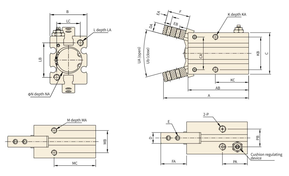
Specification
| Bore Size | A | AB | B | C | CA | D | DA | E | EA | EB | F | FA | K | KA | KB | KC | L |
| 10 | 52.5 | 38.5 | 16.5 | 23 | 14 | 6.4 | 4 | M2.5×0.45 | 3 | 5.7 | 12 | 14.5 | M3×0.5 | 5 | 16 | 23 | M3×0.5 |
| 16 | 62.5 | 44.5 | 23.6 | 30.5 | 24 | 8 | 7 | M3×0.5 | 4 | 7 | 16 | 19 | M4×0.7 | 7 | 24 | 24.5 | M4×0.7 |
| 20 | 78 | 55 | 27.6 | 42 | 30 | 10 | 8 | M4×0.7 | 5 | 9 | 20 | 23.5 | M5×0.8 | 8 | 30 | 29 | M5×0.8 |
| 25 | 92 | 60.5 | 33.6 | 52 | 36 | 12 | 10 | M5×0.8 | 8 | 12 | 27 | 33 | M6×1.0 | 10 | 36 | 30 | M6×1.0 |
| Bore Size | LA | LB | LC | M | MA | MB | MC | N | NA | P | PA | PB | UK(open) | UK(open) |
| 10 | 6 | 18 | 12 | M3×0.5 | 6 | 11.4 | 27 | 11+0.050 | 1.5 | M3×0.5 | 19 | 10 | 30° | 10° |
| 16 | 8 | 22 | 15 | M4×0.7 | 4.5 | 16 | 30 | 17+0.050 | 1.5 | M5×0.8 | 18.5 | 13 | 30° | 10° |
| 20 | 10 | 32 | 18 | M5×0.8 | 8 | 18.6 | 35 | 21+0.050 | 1.5 | M5×0.8 | 22 | 15 | 30° | 10° |
| 25 | 12 | 40 | 22 | M6×1.0 | 10 | 22 | 36.5 | 26+0.050 | 1.5 | M5×0.8 | 23.5 | 20 | 30° | 10° |
No 1.Xingjia Road, Pneumatic industrial park, Xikou,Ningbo, Zhejiang Zip code 315502
+86-574-88869818
+86-574-88869826
+86-574-88869817
+86-574-88869816
+86-574-88869833
royshan@jelpc.com

Copyright Ningbo Jiaerling Pneumatic Machinery Co.,Ltd.. All Rights Reserved. 
China Proportional Valves Manufacturers
 简体中文
简体中文 English
 日本語
日本語 한국어
한국어 Deutsch