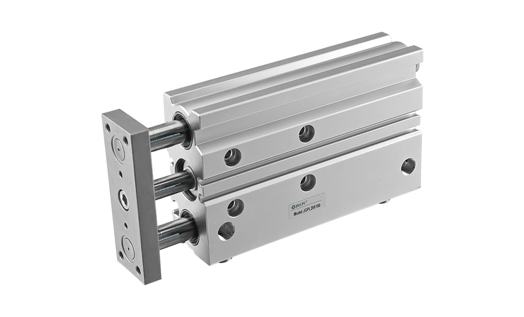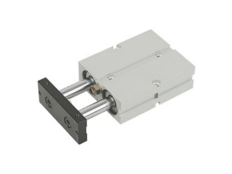

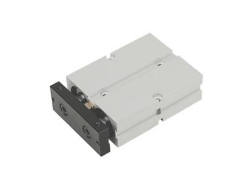
Features:
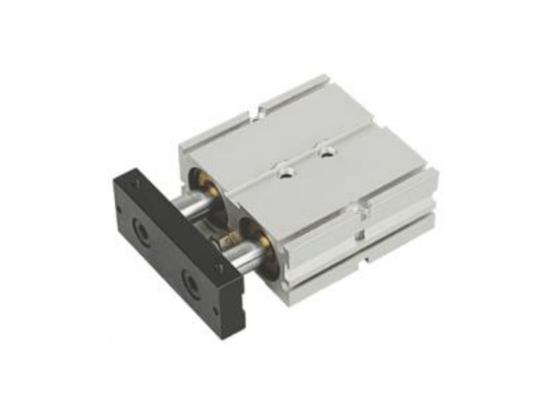
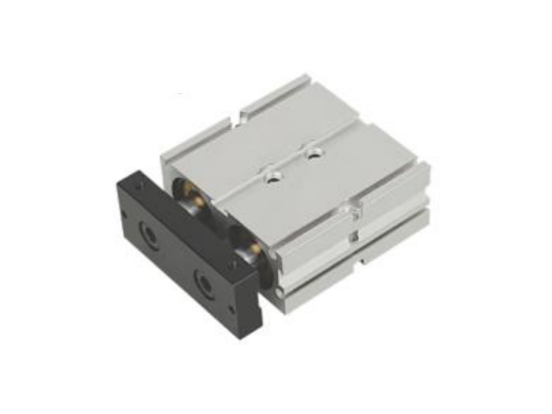
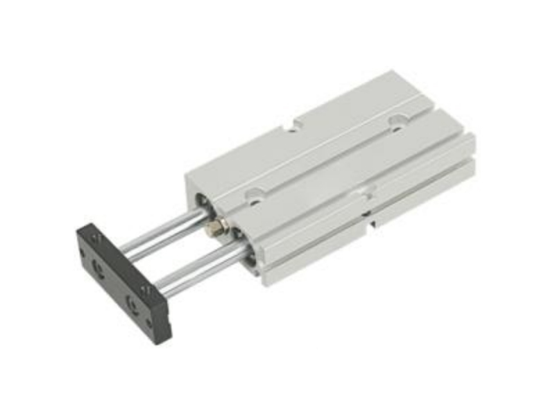
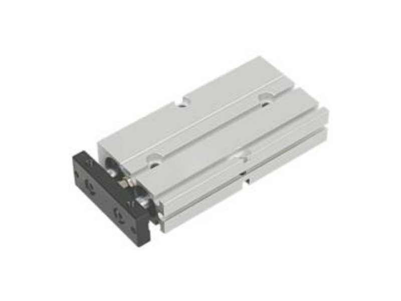
Double rod with double force for higher anti-bending and anti-twisted strength ensured durable life and perfect directional characteristics.
Internal Structure
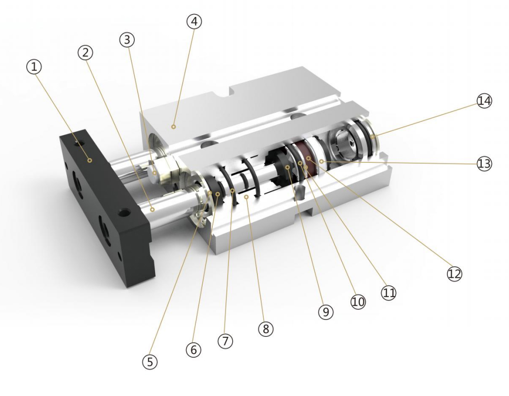
Parts
| Number | Name | Number | Name |
| 1 | Fixing plate | 8 | Front cover |
| 2 | Piston rod | 9 | Anti-collision washer |
| 3 | Anti-collision head | 10 | Piston seal |
| 4 | Cylinder body | 11 | Piston |
| 5 | Circlips for holes | 12 | Magnet |
| 6 | Shaft seal | 13 | Anti-friction ring |
| 7 | O ring | 14 | Back cover |
Ordering Code
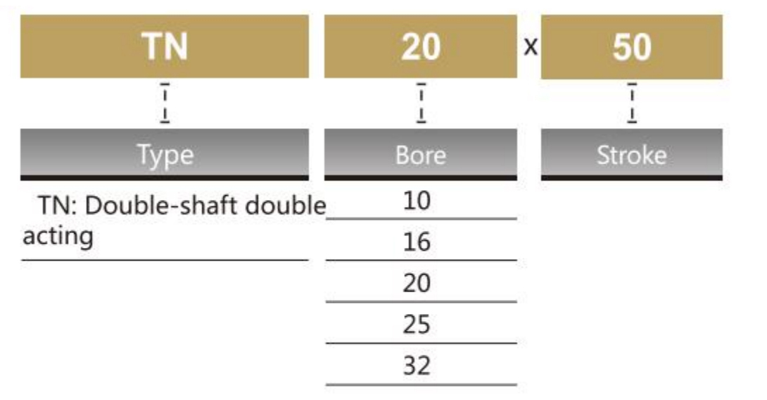
*TN Series attached magnetic ring.
*Sensor model JEL-1l,please refer to P173 for the specific ordering code.
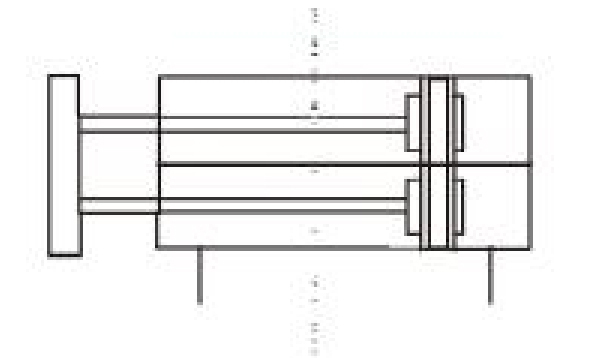
Symbol
Specification
|
Bore (mm) |
10 |
16 |
20 |
25 |
32 |
|
Working Medium |
Air |
||||
|
Operation |
Double Acting |
||||
|
Operation Pressure Range |
0.15~1.0MPa |
||||
|
Ensure Pressure Resistance |
1.5MPa |
||||
|
Operation Temperature Range |
-10~70°C |
||||
|
Operation Speed Range |
30~500 mm/s |
||||
|
Adjustable Stroke |
-10〜0 mm |
||||
|
Cushion |
Not Available |
Cushion Gasket |
|||
|
Presion Of Non-Rotating |
±0.4° |
±0.3° |
|||
|
Port Size |
M5x0.8 |
1/8 |
|||
*The Max. operating pressure is subject to the Max. load of hydralic buffer.
Stroke
| Bore (mm) | Standard Stroke | Max.Stroke | Allowable Stroke |
| 10 | 10 20 30 40 50 6070 | 70 | 100 |
| 16 | 10 20 30 40 50 60 70 80 90 100 125150 | 150 | 200 |
| 20 | 10 20 30 40 50 60 70 80 90 100 125 150 | 150 | 200 |
| 25 | 10 20 30 40 50 60 70 80 90 100 125 150 | 150 | 200 |
| 32 | 10 20 30 40 50 60 70 80 90 100 125 150 | 150 | 200 |
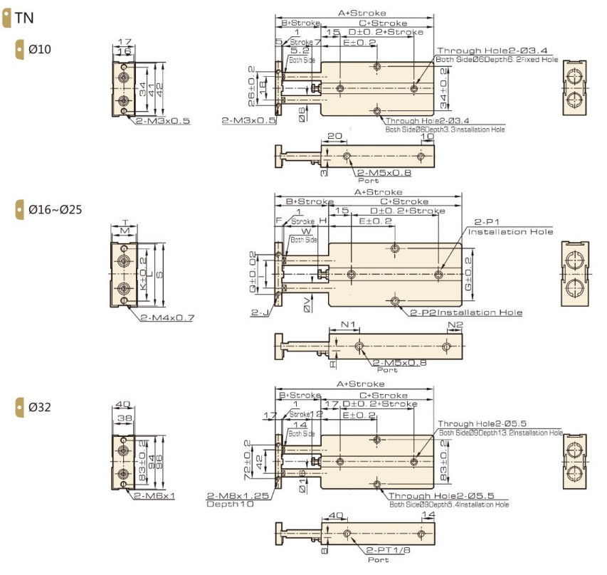
Overall Dimension
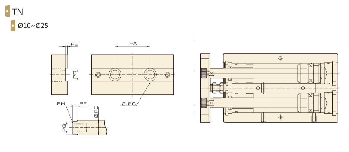
Dimension
| Bore/Symbol | PA | PB | PC | PD | PE | PF | PG | PH |
| 10 | 18 | 0.5 | ∅6.2 deep 3.5 mm, Through Hole:∅4.5 | 5.2 | 6 | 3 | 5 | M3×0.5 deep 5mm |
| 16 | 24 | 1 | ∅7.8 deep 4.6 mm, Through Hole:∅4.5 | 6.2 | 8 | 3 | 6 | M4×0.7 deep 46mm |
| 20 | 28 | 1 | ∅11 deep 6.8 mm, Through Hole:∅4.5 | 8.2 | 10 | 3 | 8 | M6×1 deep 48mm |
| 25 | 34 | 1 | ∅11 deep 6.8mm, Through Hole:∅4.5 | 10.2 | 12 | 3 | 10 | M6×1 deep 48mm |
| 32 | 42 | 2 | ∅17 deep 12 mm, Through Hole:∅4.5 | 14.2 | 16 | 3 | 14 | M10×1.5 deep 14mm |
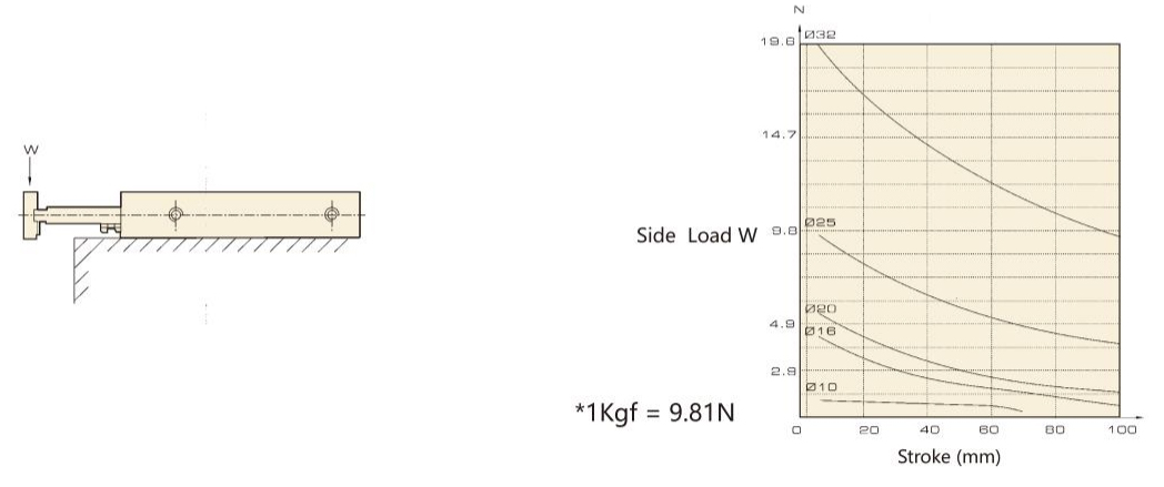
Allowable size load
Overall Dimension
|
Bore Symbol |
A |
B |
C |
D |
E |
F |
G |
H |
I |
|||||||||||
|
10 |
20 |
30 |
40 |
50 |
60 |
70 |
80 |
90 |
100 |
125 |
150 |
|||||||||
|
16 |
68 |
15 |
53 |
20 |
30 |
35 |
40 |
45 |
50 |
55 |
60 |
65 |
70 |
75 |
87.5 |
100 |
8 |
47 |
6 |
24 |
|
20 |
78 |
20 |
58 |
20 |
35 |
35 |
40 |
45 |
50 |
55 |
60 |
65 |
70 |
75 |
87.5 |
100 |
10 |
55 |
9 |
28 |
|
25 |
81 |
19 |
62 |
30 |
40 |
40 |
45 |
50 |
55 |
60 |
65 |
70 |
75 |
80 |
92.5 |
105 |
10 |
66 |
8 |
34 |
| Bore Symbol | J | K | L | M | N1 | N2 | P1 | P2 | Q | R | S | T | V | W |
| 16 | M4×0.7 deep 5 | 47 | 53 | 20 | 22 | 10 | Double side:∅7.5 Deep:7.2mm, Through Hole:∅4.5 | Double side: ∅8 Deep:4.4mm, Through Hole: ∅4.5 | 34 | 3 | 54 | 21 | 8 | 6.2 |
| 20 | M4×0.7 deep 5 | 55 | 61 | 24 | 25 | 12 | Double side:∅7.5 Deep:7.2mm, Through Hole:∅4.5 | Double side: ∅8 Deep: 4.4mm, Through Hole: ∅4.5 | 44 | 3.5 | 62 | 25 | 10 | 8. 1 |
| 25 | M4×0.8 deep 6 | 66 | 72 | 27 | 30 | 12 | Double side:∅7.5 Deep:7.2mm, Through Hole:∅4.5 | Double side: ∅8 Deep:4.4mm, Through Hole: ∅4.5 | 56 | 7 | 73 | 30 | 12 | 10.2 |
| Bore Symbol | A | B | C | D | E | |||||||||||||||
| 10 | 20 | 30 | 40 | 50 | 60 | 70 | ||||||||||||||
| 10 | 63 | 12 | 51 | 10 | 30 | 30 | 35 | 40 | 45 | 50 | 55 | |||||||||
| 32 | 108 | 30 | 78 | 35 | 10 | 20 | 30 | 40 | 50 | 60 | 70 | 80 | 90 | 100 | 125 | 150 | ||||
| 45 | 50 | 55 | 60 | 65 | 70 | 75 | 80 | 85 | 90 | 102.5 | 115 | |||||||||
No 1.Xingjia Road, Pneumatic industrial park, Xikou,Ningbo, Zhejiang Zip code 315502
+86-574-88869818
+86-574-88869826
+86-574-88869817
+86-574-88869816
+86-574-88869833
royshan@jelpc.com

Copyright Ningbo Jiaerling Pneumatic Machinery Co.,Ltd.. All Rights Reserved. 
China Proportional Valves Manufacturers
 简体中文
简体中文 English
 日本語
日本語 한국어
한국어 Deutsch