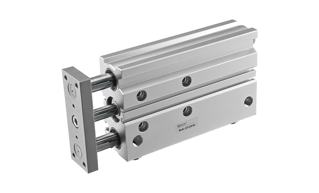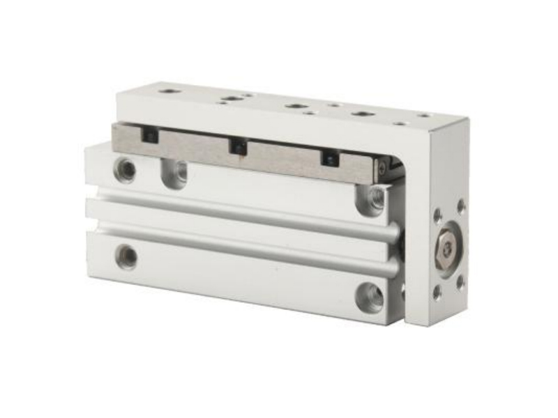

Features:
1. Adopt high rigidity and elongated guide rail to improve cylinder rigidity and guiding accuracy.
2. Standard built-in magnetic ring, can be installed stroke sensing switch.
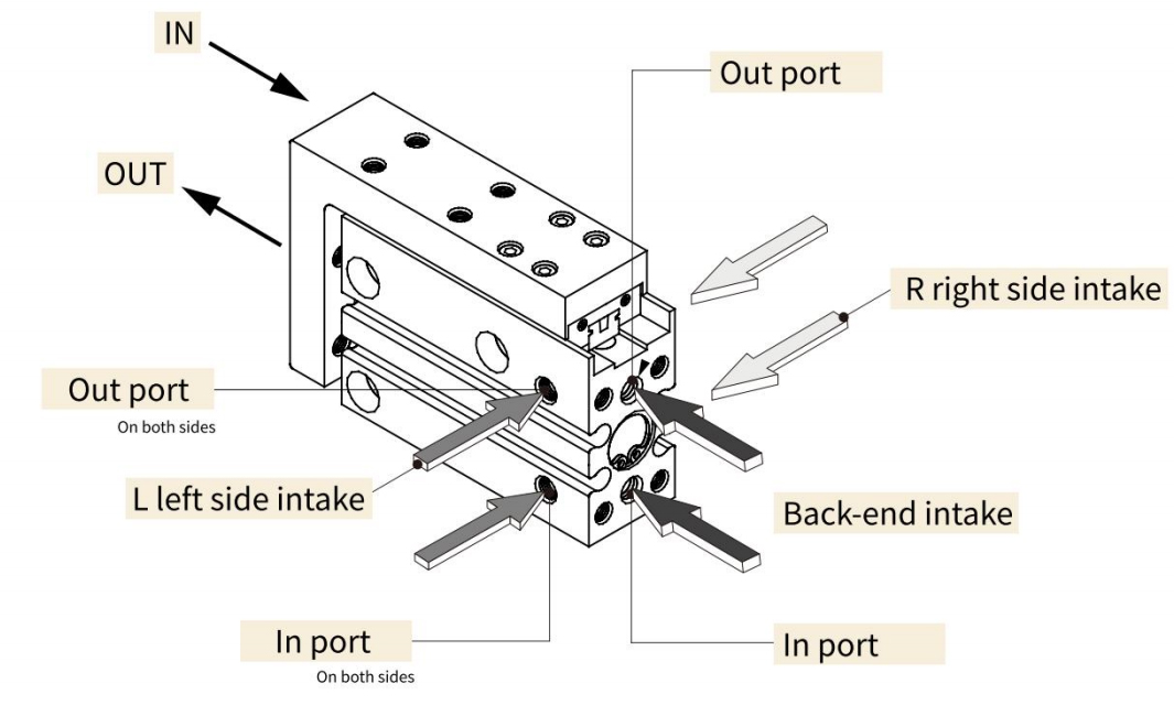
3. Piping is possible in 3 directions.
4. Sensor can be mounted on both sides.
5. Standard rubber buffer on both ends.
Specification
| Bore Size(mm) | 6 | 10 | 16 | 20 | |
| Working Medium | Air | ||||
| Action | Double acting | ||||
| Min. Operating Pressure | 0.15MPa | 0.1MPa | |||
| Max. Operating Pressure | 0.7MPa | ||||
| Ambient And Fluid Temperature | 10~60℃(with no condensation) | ||||
| Piston Speed | 50~500 mm/s | ||||
| Allowable Kinetic Energy J | 0.0125 | 0.025 | 0.05 | 0.1 | |
| Lubrication | No need | ||||
| Cushing | Rubber cushion on both ends +1.0 0 |
||||
| Stroke Length Tolerance(mm) | |||||
| Sensor Model | JEL-07D | ||||
| Piping Size | M5×0.8 | ||||
Model Representation
Piping ls Possible In 3 Directions
Ordering Code
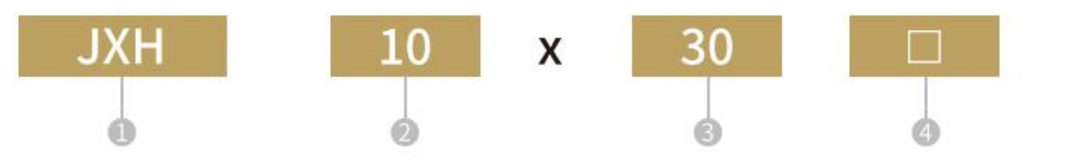
| ①Model | ② Bore Size | ③ Stroke | ④ Stroke |
| JXH | See the stroke/sensor table for details | Nil | |
| L | |||
| R | |||
[Note]Sensor model please refer to P173 for the specific ordering code.
Stroke/Sensor
| Model | Bore Size(mm) | Standard Stroke(mm) | Direct Mounting Sensor |
| JXH | 6 | 5 10 15 20 25 30 40 50 60 | JEL-07D |
| 10 | |||
| 16 | |||
| 20 |
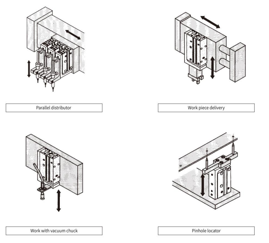
Application
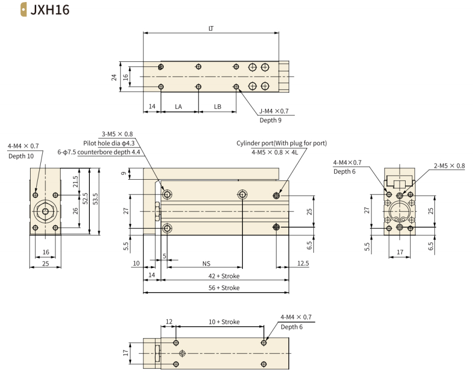
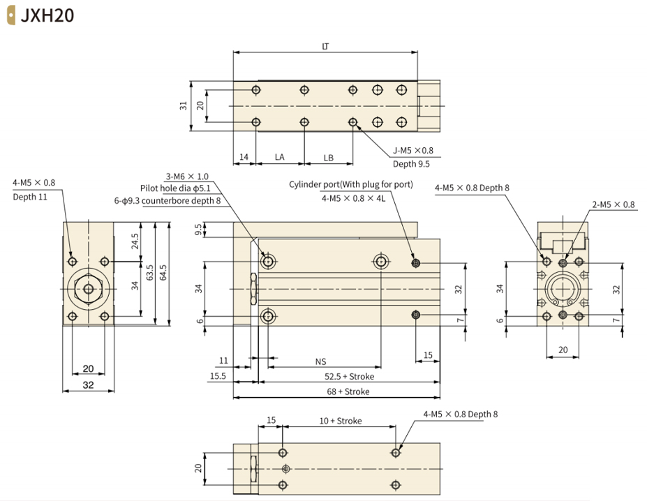
Overall Dimension
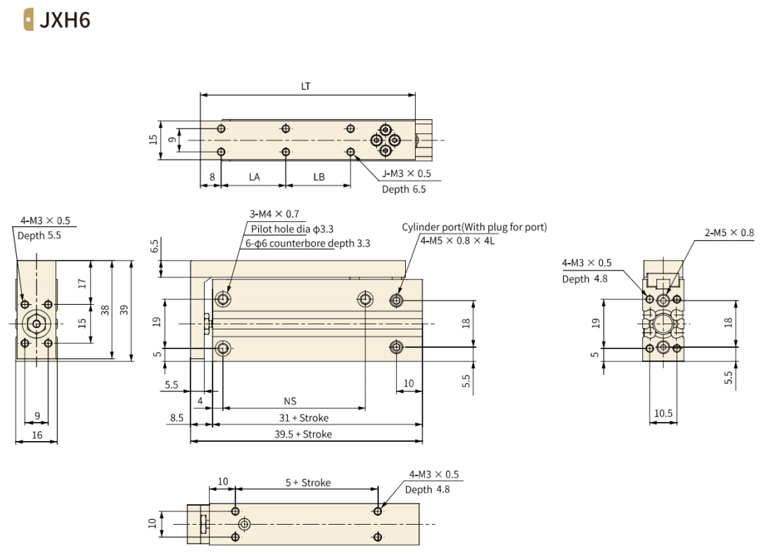
| Stroke | J | LA | LB | LT | NS |
| 5 | 4 | 10 | - | 42 | 14 |
| 10 | 4 | 10 | - | 42 | 14 |
| 15 | 4 | 20 | - | 52 | 24 |
| 20 | 4 | 20 | - | 52 | 24 |
| 25 | 4 | 30 | - | 62 | 30 |
| 30 | 4 | 30 | - | 62 | 30 |
| 40 | 6 | 20 | 20 | 72 | 45 |
| 50 | 6 | 25 | 25 | 82 | 55 |
| 60 | 6 | 30 | 30 | 92 | 60 |
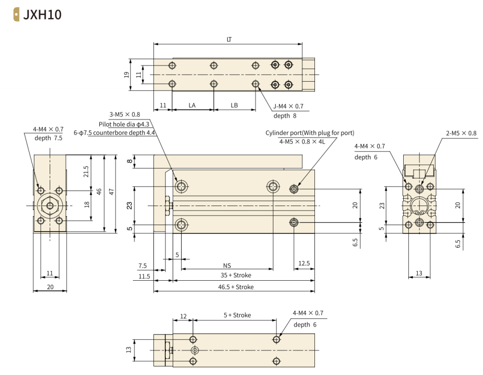
| Stroke | J | LA | LB | LT | NS |
| 5 | 4 | 10 | - | 49 | 14 |
| 10 | 4 | 10 | - | 49 | 14 |
| 15 | 4 | 20 | - | 59 | 24 |
| 20 | 4 | 20 | - | 59 | 24 |
| 25 | 4 | 30 | - | 69 | 30 |
| 30 | 4 | 30 | - | 69 | 30 |
| 40 | 6 | 20 | 20 | 79 | 45 |
| 50 | 6 | 25 | 25 | 89 | 55 |
| 60 | 6 | 30 | 30 | 99 | 60 |
|
Stroke |
J |
LA |
LB |
LT |
NS |
|
5 |
4 |
10 |
- |
58 |
20 |
|
10 |
4 |
10 |
- |
58 |
20 |
|
15 |
4 |
20 |
- |
68 |
30 |
|
20 |
4 |
20 |
- |
68 |
30 |
|
25 |
4 |
30 |
- |
78 |
40 |
|
30 |
4 |
30 |
- |
78 |
40 |
|
40 |
6 |
20 |
20 |
88 |
50 |
|
50 |
6 |
25 |
25 |
98 |
60 |
|
60 |
6 |
30 |
30 |
108 |
60 |
|
Stroke |
J |
LA |
LB |
LT |
NS |
|
5 |
4 |
10 |
- |
64 |
20 |
|
10 |
4 |
10 |
- |
64 |
20 |
|
15 |
4 |
20 |
- |
74 |
25 |
|
20 |
4 |
20 |
- |
74 |
25 |
|
25 |
4 |
30 |
- |
84 |
40 |
|
30 |
4 |
30 |
- |
84 |
40 |
|
40 |
6 |
20 |
20 |
94 |
50 |
|
50 |
6 |
25 |
25 |
104 |
70 |
|
60 |
6 |
30 |
30 |
114 |
70 |
Operating Precautions
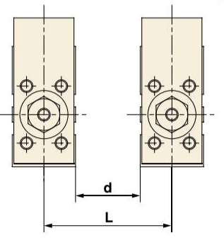
1. When multiple cylinders are installed, a certain distance between the cylinders is required to avoid misoperation. For details, see the following table.
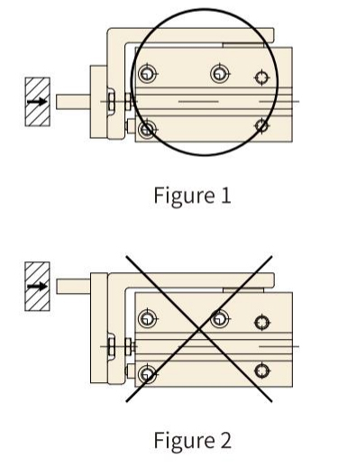
2. If the cylinder is moving by the external limit, the reaction force generated at the limit should coincide with the axial direction of the cylinder piston rod (as shown in Figure 1), if it does not coincide, it will produce a large torque and reduce the service life, such as the guide rail will be damaged (as shown in Figure 2).
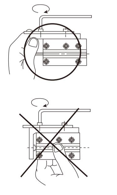
3. Hold the table when fastening work pieces to it with bolts etc. If the body is held while tightening bolts etc., the guide section will be subjected to a large moment, and there may be a loss of precision.
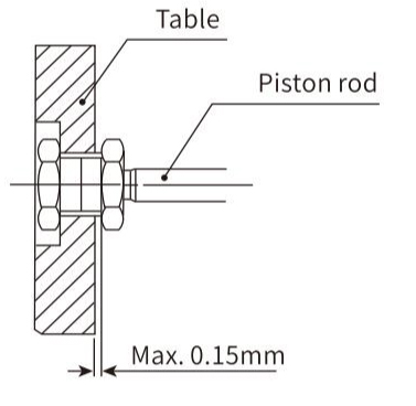
4. Since the connection between the piston rod and table is a floating mechanism, the table has backlash of 0.15mm or less in the stroke direction.(Refer to the figure below.)
No 1.Xingjia Road, Pneumatic industrial park, Xikou,Ningbo, Zhejiang Zip code 315502
+86-574-88869818
+86-574-88869826
+86-574-88869817
+86-574-88869816
+86-574-88869833
royshan@jelpc.com

Copyright Ningbo Jiaerling Pneumatic Machinery Co.,Ltd.. All Rights Reserved. 
China Proportional Valves Manufacturers
 简体中文
简体中文 English
 日本語
日本語 한국어
한국어 Deutsch