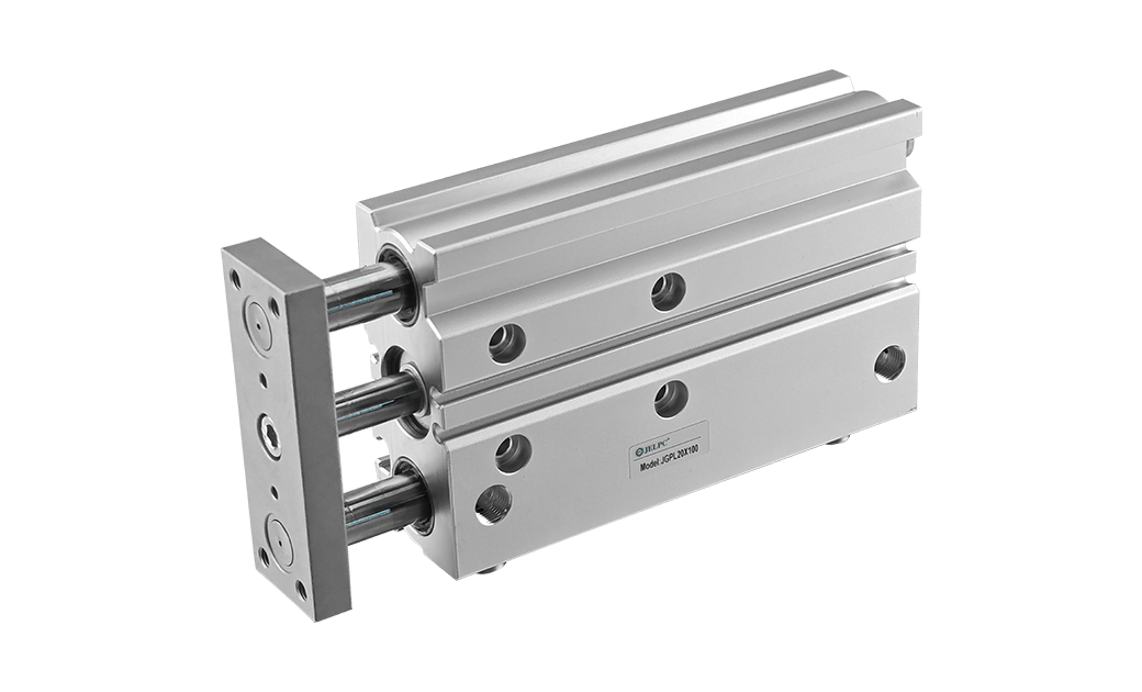

Feature:
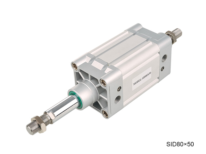
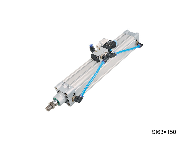
1. The cylinder is in accordance with the lSO15552
2. The piston seal adopts two NBR+PA material as Y type one-way sealing structure with compensation function, long service life and low starting pressure.
3. The rod seal uses PU material with the characteristics of high strength, good toughness, wear resistance. oil resistance and aging resistance.
4. The piston rod material is made by 45C Carbon Steel with hard chrome plating on the surface, and the roughness Ra<0.4, with good wear resistance and rust resistance.
Internal Structure
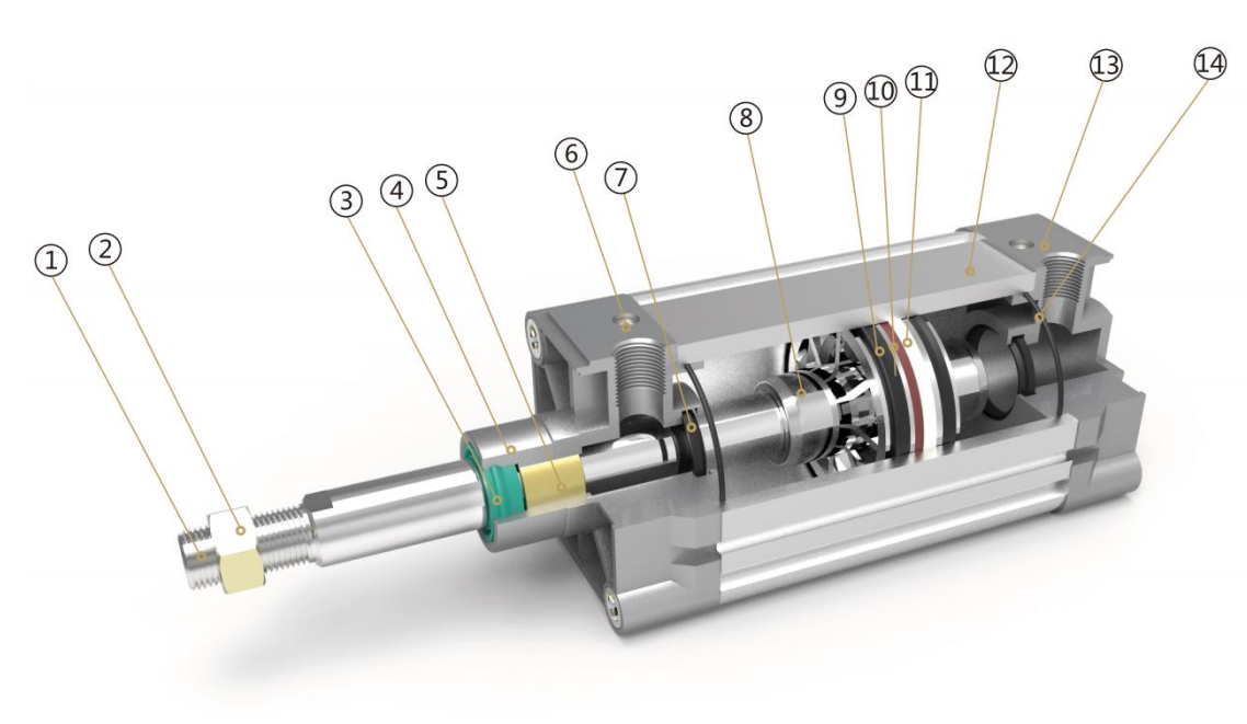
Parts
| Number | Name | Number | Name |
| 1 | Piston rod | 8 | Piston |
| 2 | Hexagon nut | 9 | Y ring |
| 3 | Shaft seal | 10 | Magnet |
| 4 | Front cover | 11 | Anti-friction ring |
| 5 | Copper tube | 12 | Barrel |
| 6 | Cushion adjust screw | 13 | Back cover |
| 7 | Cushion seal | 14 | O ring |
Ordering Code
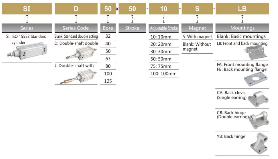
*Sensor model JEL-30, please refer to P173 for the specific ordering code.
Specification
| Bore (mm) | 32 | 40 | 50 | 63 | 80 | 100 | 125 |
| Operation | Double Acting | ||||||
| Working Medium | Air | ||||||
| Mountings | Basic FA FB CA CB LB YB | ||||||
| Operating Pressure Range | 1~9.0 Kgf/cm² | ||||||
| Proof Pressure | 13.5 Kgf/cm² | ||||||
| Operating Temperature Range | -20~80℃ | ||||||
| Operating Speed Range | 50~800mm/s | ||||||
| Cushion | Adjustable Cushion | ||||||
| Adjustable Cushion Stroke | 20mm | 26mm | |||||
| Port Size | G1/8" | G1/4" | G3/8" | G1/2” | |||
Stroke
| Bore | Standard Stroke | Max.Stroke | Allowable Stroke |
| 32 | 25 50 75 80 100 125 150 160 175 200 250 300 350 400 450 500 | 1000 | 2000 |
| 40 | 25 50 75 80 100 125 150 160 175 200 250 300 350 400 450 500 600 700 800 | 1200 | 2000 |
| 50 | 25 50 75 80 100 125 150 160 175 200 250 300 350 400 450 500 600 700 800 900 1000 | 1200 | 2000 |
| 63 | 25 50 75 80 100 125 150 160 175 200 250 300 350 400 450 500 600 700 800 900 1000 | 1500 | 2000 |
| 80 | 25 50 75 80 100 125 150 160 175 200 250 300 350 400 450 500 600 700 800 900 1000 | 1500 | 2000 |
| 100 | 25 50 75 80 100 125 150 160 175 200 250 300 350 400 450 500 600 700 800 900 1000 | 1500 | 2000 |
| 125 | 25 50 75 80 100 125 150 160 175 200 250 300 350 400 450 500 600 700 800 900 1000 | 1500 | 2000 |
Overall Dimension
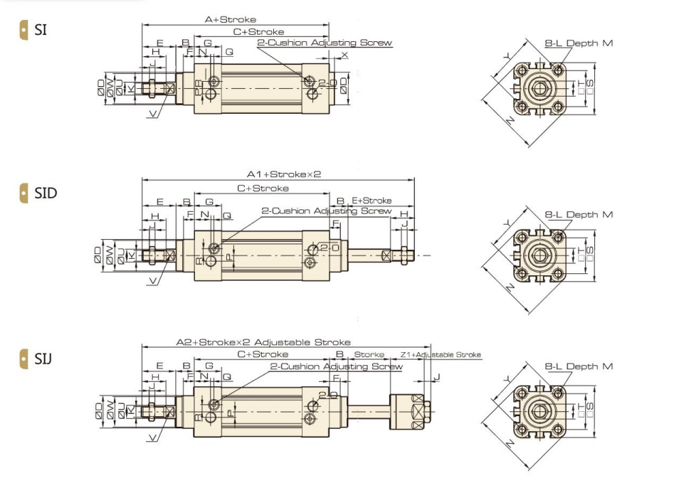
Dimension
| Bore/Symbol | A | A1 | A2 | B | C | D | E | F | G | H | I | J | K | L |
| 32 | 143 | 190 | 185 | 16 | 94 | 30 | 33 | 10 | 25 | 22 | 17 | 6 | M10×1.25 | M6 |
| 40 | 159 | 213 | 207 | 20 | 105 | 35 | 34 | 10 | 29.5 | 24 | 17 | 7 | M12x1.25 | M6 |
| 50 | 175 | 244 | 233 | 27 | 107 | 40 | 42 | 10 | 32 | 32 | 23 | 8 | M16x1.5 | M8 |
| 63 | 190 | 258 | 247 | 26 | 122 | 45 | 42 | 10 | 36 | 32 | 23 | 8 | M16x1.5 | M8 |
| 80 | 214 | 301 | 288 | 35 | 126 | 45 | 53 | 10 | 37 | 40 | 26 | 10 | M20×1.5 | M10 |
| 100 | 229 | 321 | 308 | 40 | 137 | 55 | 52 | 10 | 39 | 40 | 26 | 10 | M20x1.5 | M10 |
| 125 | 279 | 394 | 378 | 47 | 160 | 60 | 72 | 10 | 43 | 54 | 40 | 12 | M27x2 | M12 |
| Bore/ Symbol | M | N | O | P | Q | R | S | T | U | V | W | X | Y | Z | Z1 |
| 32 | 12 | 15 | G1/8 | 5 | 3 | 6.5 | 45 | 32.5 | 12 | 10 | 28 | 4 | 46 | 58.7 | 21 |
| 40 | 12 | 17.5 | G1/4 | 7 | 3 | 7 | 52 | 38 | 16 | 13 | 33 | 4 | 53.7 | 68 | 21 |
| 50 | 12 | 20 | G1/4 | 7 | 3 | 9 | 65 | 46.5 | 20 | 17 | 38 | 4 | 65.8 | 84.5 | 23 |
| 63 | 12 | 22 | G3/8 | 8 | 5 | 9 | 76 | 56.5 | 20 | 17 | 38 | 4 | 79.9 | 99.6 | 23 |
| 80 | 15 | 23 | G3/8 | 10 | 5 | 12 | 94 | 72 | 25 | 22 | 43.5 | 4 | 101.8 | 123.8 | 29 |
| 100 | 15 | 26 | G1/2 | 10 | 5 | 14 | 112 | 89 | 25 | 22 | 47 | 4 | 125.9 | 148.9 | 29 |
| 125 | 20 | 29 | G1/2 | 10 | 5 | 14 | 134 | 110 | 32 | 27 | 53 | 6 | 156.9 | 179.6 | 40.5 |
LB Foot Overall Dimension
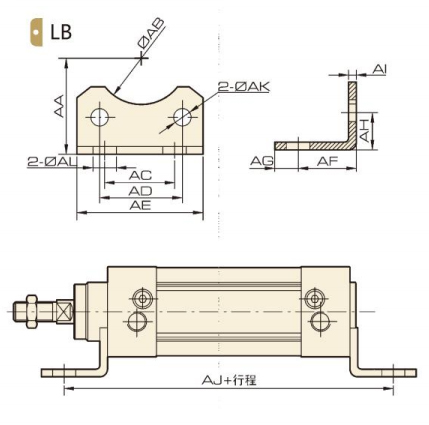
Dimension
| Bore/Symbol | 32 | 40 | 50 | 63 | 80 | 100 | 125 |
| AA | 32 | 36 | 45 | 50 | 63 | 71 | 90 |
| AB | 30 | 35 | 40 | 45 | 45 | 55 | 60 |
| AC | 32 | 36 | 45 | 50 | 63 | 75 | 90 |
| AD | 32.5 | 38 | 46.5 | 56.5 | 72 | 89 | 110 |
| AE | 45 | 52 | 65 | 75 | 95 | 115 | 140 |
| AF | 24 | 28 | 32 | 32 | 41 | 41 | 45 |
| AG | 11 | 8 | 15 | 13 | 14 | 16 | 18 |
| AH | 15.8 | 17 | 21.8 | 21.8 | 27 | 26.5 | 35 |
| AI | 4 | 4 | 5 | 5 | 6 | 6 | 7 |
| AJ | 142 | 161 | 170 | 186 | 208 | 219 | 250 |
| AK | 7 | 7 | 9 | 9 | 11 | 11 | 12.5 |
| AL | 7 | 10 | 10 | 10 | 12 | 14.5 | 16.5 |
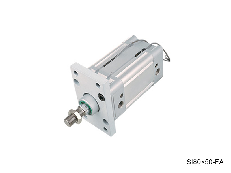
FA / FB Flange Overall Dimension
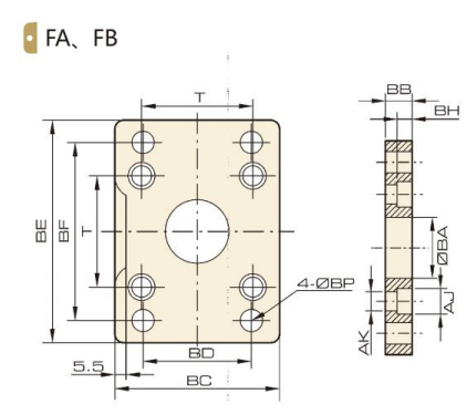
Dimension
| Bore/Symbol | 32 | 40 | 50 | 63 | 80 | 100 | 125 |
| BA | 30.3 | 35.3 | 40.3 | 45.3 | 45.3 | 55.3 | 60.3 |
| BB | 10 | 10 | 12 | 12 | 16 | 16 | 20 |
| BC | 45 | 52 | 65 | 76 | 94 | 112 | 140 |
| BD | 32 | 36 | 45 | 50 | 63 | 75 | 90 |
| BE | 80 | 90 | 110 | 120 | 150 | 175 | 224 |
| BF | 64 | 72 | 90 | 100 | 126 | 150 | 180 |
| BH | 6.5 | 6.5 | 8.5 | 8.5 | 10.5 | 10.5 | 15 |
| AJ | 10.5 | 10.5 | 13.5 | 13.5 | 16.5 | 16.5 | 19 |
| AK | 6.5 | 6.5 | 8.5 | 8.5 | 10.5 | 10.5 | 12.5 |
| BP | 7 | 9 | 9 | 9 | 12 | 14 | 16 |
| T | 32.5 | 38 | 46.5 | 56.5 | 72 | 89 | 110 |
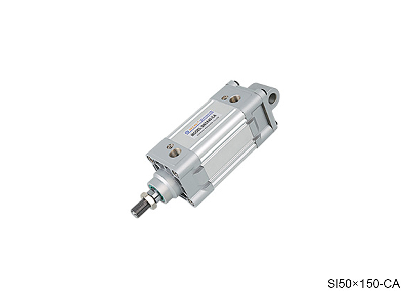
CA Hinge Overall Dimension
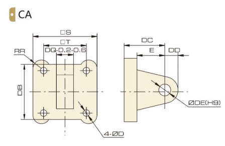
Dimension
| Bore/Symbol | 32 | 40 | 50 | 63 | 80 | 100 | 125 |
| S | 45 | 52 | 65 | 76 | 94 | 112 | 140 |
| T | 32.5 | 38 | 46.5 | 56.5 | 72 | 89 | 110 |
| RR | 6.5 | 6.5 | 9 | 9.5 | 11 | 11.5 | 12 |
| DB | 34 | 41 | 54 | 65 | 83 | 101 | 123 |
| DC | 22 | 25 | 27 | 32 | 36 | 41 | 50 |
| DD | 10 | 11 | 13 | 16 | 16 | 20 | 25 |
| DE | 10 | 12 | 12 | 16 | 16 | 20 | 25 |
| DQ | 26 | 28 | 32 | 40 | 50 | 60 | 70 |
| D | 6.5 | 6.5 | 8.5 | 8.5 | 10.5 | 10.5 | 12.5 |
| E | 14 | 17 | 17 | 22 | 24 | 25 | 30 |
CB Hinge Overall Dimension
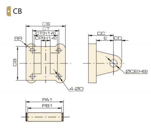
Dimension
| Bore/Symbol | 32 | 40 | 50 | 63 | 80 | 100 | 125 |
| S | 45 | 52 | 65 | 76 | 94 | 112 | 140 |
| T | 32.5 | 38 | 46.5 | 56.5 | 72 | 89 | 110 |
| D | 6.5 | 6.5 | 8.5 | 8.5 | 10.5 | 10.5 | 12.5 |
| E | 14 | 17 | 17 | 22 | 24 | 25 | 30 |
| RR | 6.5 | 6.5 | 9 | 9.5 | 11 | 11.5 | 12 |
| CB | 34 | 41 | 54 | 65 | 83 | 101 | 123 |
| CC | 22 | 25 | 27 | 32 | 36 | 41 | 50 |
| CD | 10 | 11 | 13 | 16 | 46 | 20 | 25 |
| CE | 10 | 12 | 12 | 16 | 16 | 20 | 25 |
| CP | 26 | 28 | 32 | 40 | 50 | 60 | 70 |
| CT | 45 | 52 | 60 | 70 | 90 | 110 | 120 |
| PA1 | 53 | 60 | 68 | 78 | 100 | 120 | 130 |
| PB1 | 46.5 | 53.5 | 61.5 | 71.5 | 91.5 | 111.5 | 121.5 |
YB Hinge Overall Dimension
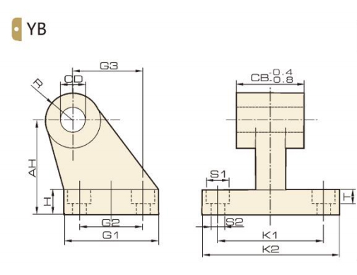
Dimension
| Bore/Symbol | 32 | 40 | 50 | 63 | 80 | 100 |
| AH | 32 | 36 | 45 | 50 | 63 | 71 |
| H | 8 | 10 | 12 | 12 | 14 | 15 |
| CD | 10 | 12 | 12 | 16 | 16 | 20 |
| G1 | 31 | 35 | 45 | 50 | 60 | 70 |
| G2 | 18 | 22 | 30 | 35 | 40 | 50 |
| G3 | 21 | 24 | 33 | 37 | 47 | 55 |
| CB | 26 | 28 | 32 | 40 | 50 | 60 |
| K1 | 38 | 41 | 50 | 52 | 66 | 76 |
| K2 | 51 | 54 | 65 | 67 | 86 | 96 |
| S2 | 6.6 | 6.6 | 9 | 9 | 11 | 11 |
| R | 10 | 11 | 13 | 15 | 15 | 19 |
No 1.Xingjia Road, Pneumatic industrial park, Xikou,Ningbo, Zhejiang Zip code 315502
+86-574-88869818
+86-574-88869826
+86-574-88869817
+86-574-88869816
+86-574-88869833
royshan@jelpc.com

Copyright Ningbo Jiaerling Pneumatic Machinery Co.,Ltd.. All Rights Reserved. 
China Proportional Valves Manufacturers
 简体中文
简体中文 English
 日本語
日本語 한국어
한국어 Deutsch