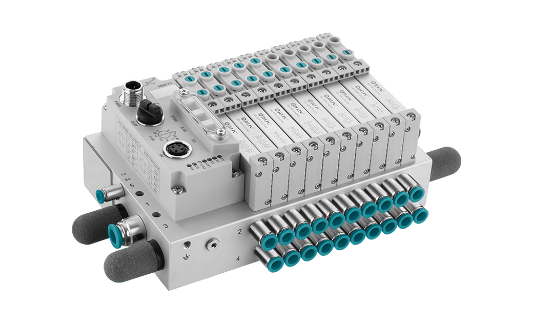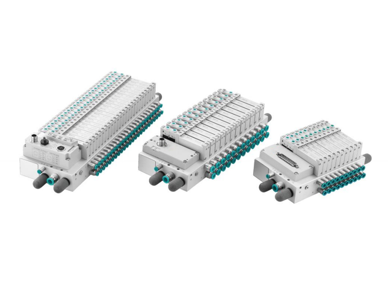
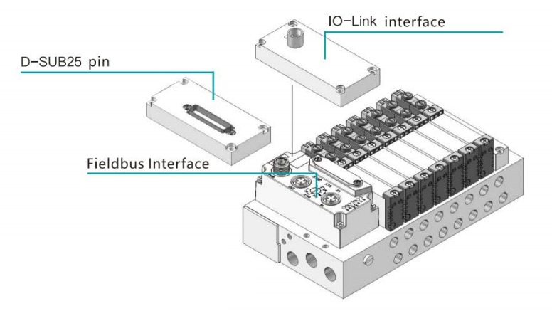
About Valve Terminal
● For modular pneumatic control systems
● Extremely flexibility and expansibilityiomm
● 14mm and 10mm widths with various functions optional
● Reduced power consumption by 70%
● Indicator light is visible at all angles for quick troubleshooting
● Up to 24 valve positions
● Protection class lp65
● Internal and external pilot structure available
Specifications
| Positions | 4,5,6,7,8,9,10,12,14,16,20,24 | ||
| Electrical Connection | D-SUB25 pin,IU-LInK,PRUHINEI.EtnerCAI,EtneriNet/IP,CC-LINKIEFela BasiC | ||
| Voltage | 24VDC±10% | ||
| Power Consumption | Single Coil Instant Max 1.2W | ||
| Flow Rate | Max600L/min(According to the valve type) | ||
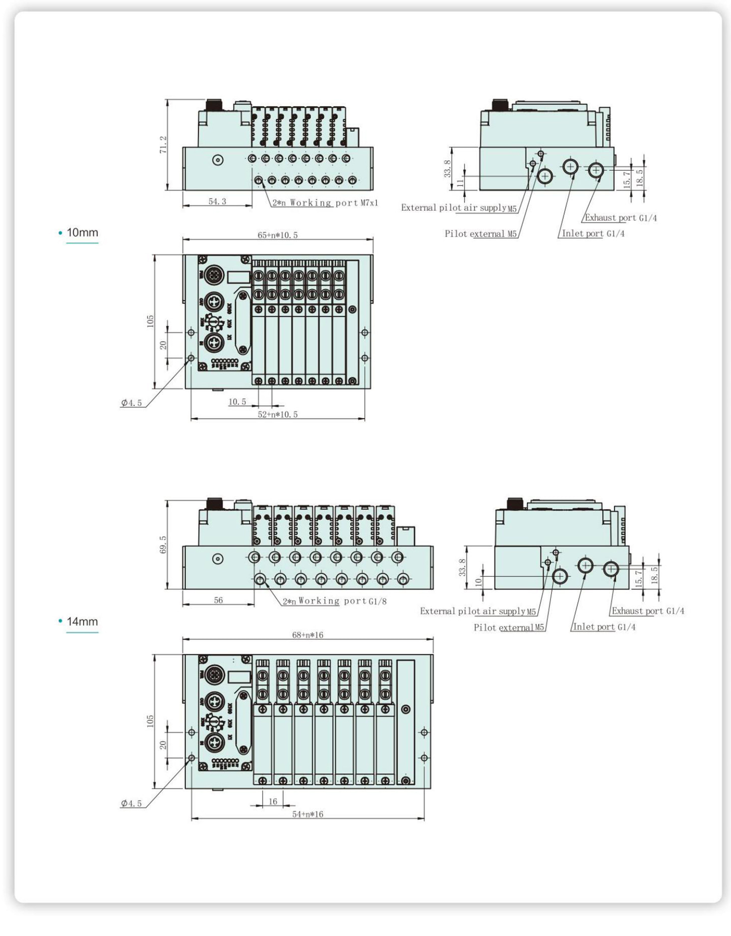
| Working Port | 10mm: Supply=Exhaust=G1/4"Working=M7*1 | 14mm:Supply=Exhaust=G1/4"Working=G1/8" | |
| Working Pressure | Pilot Pressure | Refer to P39 FDF valve specification | |
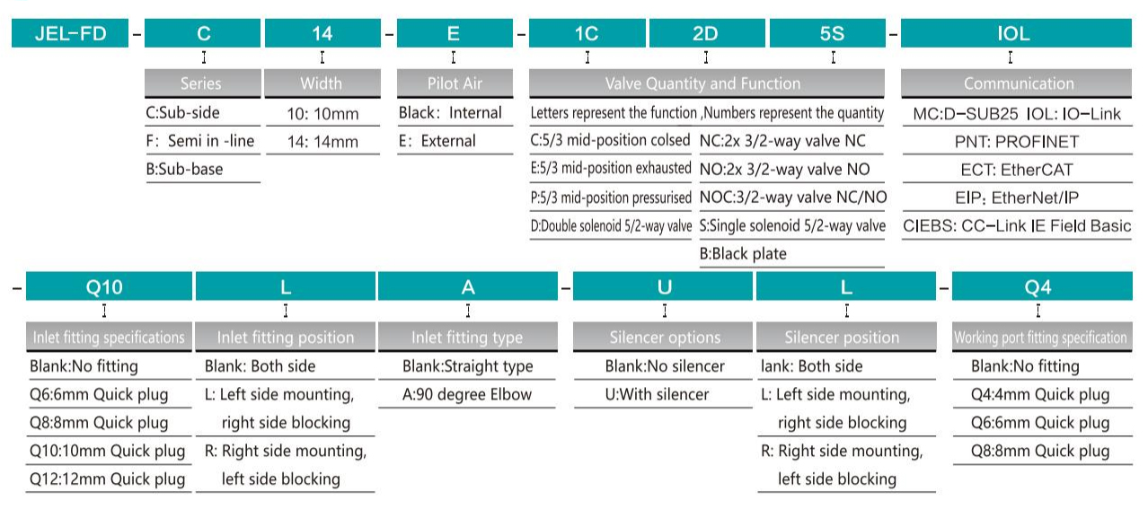
Ordering Code
Overall Dimension
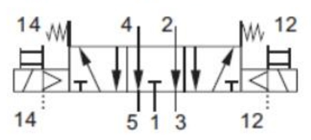
Structure Diagram
● Choice of quick push-in connectors
● Switching between different buses or control modes can be realized
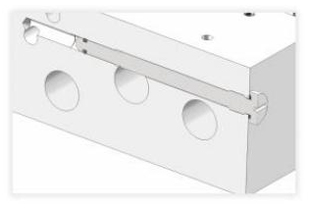
Internal and External Pilot Switching
 |
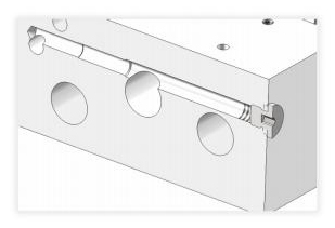 |
| External Pilot | Internal Pilot |
| Installing screw at the pilot switching hole can realize the external pilot function, pilot air through the M5 threaded hole at the end face of the bottom plate. | Installing M5 plug at the pilot switching hole can realize the internal pilot function, pilot air directly though the air inlet of the bottom plate. |
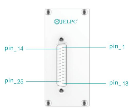
D-SUB25 pin
| Item | Order code |
| D-SUB25 pin | M1-25-SUB |
● Valve terminal can control up to 24 coils depending on the connection mode. Each valve coil of the valve terminal corresponmds to a pin on the multi-pin plug.
Definition of D-SUB25 pin module
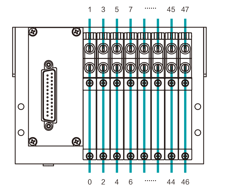
| PIN | Position | Max Valve Position | ||||
| 4~12 | 16 | 20 | 24 | |||
| Valve No. /coil Name | ||||||
| 1 | 0 | 0/14 | 0/14 | 0/14 | 0/14 | |
| 2 | 1 | 0/12 | 00/12 | 0/12 | 23/14 | |
| 3 | 2 | 1/14 | 1/14 | 1/14 | 1/14 | |
| 4 | 3 | 1/12 | 1/12 | 1/12 | 22/14 | |
| 5 | 4 | 2/14 | 2/14 | 2/14 | 2/14 | |
| 6 | 5 | 2/12 | 2/12 | 2/12 | 21/14 | |
| 7 | 6 | 3/14 | 3/14 | 3/14 | 3/14 | |
| 8 | 7 | 3/12 | 3/12 | 3/12 | 20/14 | |
| 9 | 8 | 4/14 | 4/14 | 4/14 | 4/14 | |
| 10 | 9 | 4/12 | 4/12 | 19/14 | 19/14 | |
| 11 | 10 | 5/14 | 5/14 | 5/14 | 5/14 | |
| 12 | 11 | 5/12 | 5/12 | 18/14 | 18/14 | |
| 13 | 12 | 6/14 | 6/14 | 6/14 | 6/14 | |
| 14 | 13 | 6/12 | 6/12 | 17/14 | 17/14 | |
| 15 | 14 | 7/14 | 7/14 | 7/14 | 7/14 | |
| 16 | 15 | 7/12 | 7/12 | 16/14 | 16/14 | |
| 17 | 16 | 8/14 | 8/14 | 8/14 | 8/14 | |
| 18 | 17 | 8/12 | 15/14 | 15/14 | 15/14 | |
| 19 | 18 | 9/14 | 9/14 | 9/14 | 9/14 | |
| 20 | 19 | 9/12 | 14/14 | 14/14 | 14/14 | |
| 21 | 20 | 10/14 | 10/14 | 10/14 | 10/14 | |
| 22 | 21 | 10/12 | 13/14 | 13/14 | 13/14 | |
| 23 | 22 | 11/14 | 11/14 | 11/14 | 11/14 | |
| 24 | 23 | 11/12 | 12/14 | 12/14 | 12/14 | |
| 25 | COM | |||||
● Double coil valve can be installed at the valve position corresponding to the gray area.
IO-Link Module

| Item | Order Code | Description |
| IO-Link-8 | JEL-VTE-8-PT | Up to 8 position base |
| IO-Link-16 | JEL-VTE-16-PT | Up to 16 position base |
| I0-Link-24 | JEL-VTE-24-PT | Up to 24 position base |
| IO-Link Pin Distribution | |||
| Interface | Pin | Distribution | Function |
 |
1 | 24VEL/SEN(PS) | Supply Power |
| 2 | 24V BAL/OUT(PL) | Load Power | |
| 3 | OV EL/SEN(PS) | Supply Power | |
| 4 | C/Q | Communication | |
| 5 | OV VAL/OUT(PL) | Load Power | |
| O-Link LED Indicator | Drive File IO-Link | ||||
| Green light flashes | Normal operation state | Specification | V1.1 | Output data | 2 bytes |
| Red light always on | 24V load power failure orno 10-Link signal | Data transmission rate | COM2(38.4KBit) | 4 bytes | |
| Blue light always on | Open circuit or overload | 6 bytes | |||
● Please ask for the corresponding ODD file.
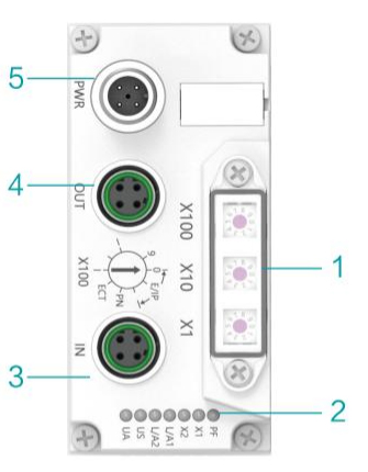
Fieldbus Module
| Item | Order Code | Description |
| Fieldbus-PNT | CTEU-PNT | PROFINET |
| Fieldbus-ECT | CTEU-ECT | EtherCAT |
| Fieldbus-EIP | CTEU-EIP | EtherNet/IP |
| Fieldbus-CIEBS | CTEU-CIEBS | CC-Link IE Field Basic |
| Fieldbus-Multiple | CTEU-MPL | Support above 4 protocols |
| NO. | Name | Description |
| 1 | Dial switch | Protocol switching, IP address and coil setting |
| 2 | LED indicator | Operation status |
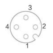
| 3 | Communication interface(IN) | M12 female D port 4 wire |
| 4 | Communication interface(OUT) | M12 female D port 4 wire |
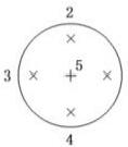
| 5 | Power interface | M12 male AportA wire, power supply of communication module and valve |
| Power source | Communication Interface(OUT) | Communication Interface(OUT) | |||||||||
 |
M12,4-pin,A-coded,male(PWR) | 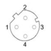 |
M12,4-pin, D-coded, plug | 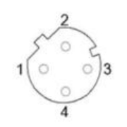 |
M12,4-pin, D-coded, plug | ||||||
| Pin | Function | Pin | Function | Pin | Function | ||||||
| 1 | UA | Actuator Power | 1 | Tx+ | Transmit Datat+ | 1 | Tx+ | Transmit Datat+ | |||
| 2 | GND | Actuator Power | 2 | Rx+ | Receive Data+ | 2 | Rx+ | Receive Data+ | |||
| 3 | US | Bus Power | 3 | Tx- | Transmit Data- | 3 | Tx- | Transmit Data- | |||
| 4 | GND | Bus Power | 4 | Rx- | Receive Data- | 4 | Rx- | Receive Data- | |||
● Please ask for the corresponding drive file.
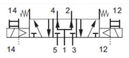
FDF Valve Specification
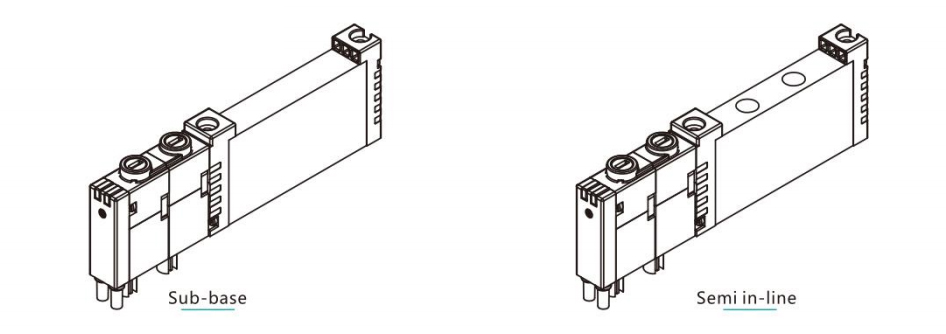
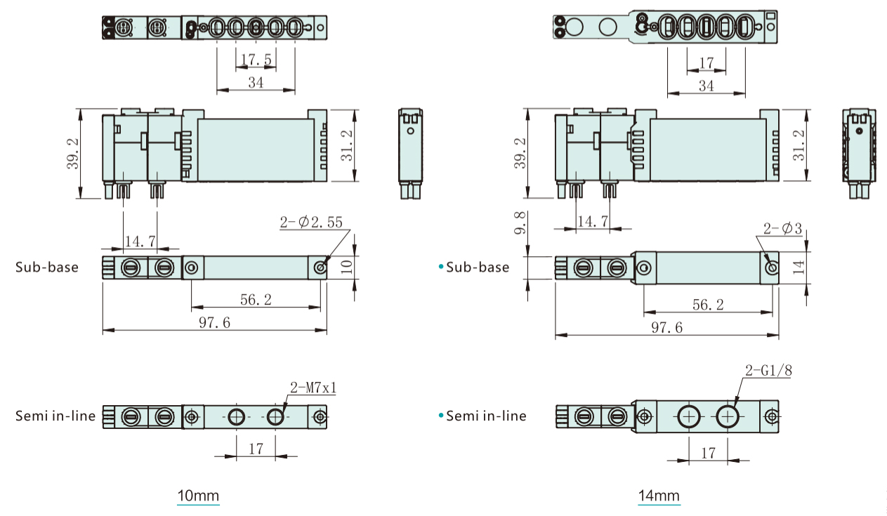
● For sub-base valve, 5 ports are all at the bottom, For semi in-line valve, inlet and exhaust ports are at the bottom 2 working ports are at the top.
● All valves are external pilot, it can be realized by switching screws on the sub-base when internal pilot is needed.
|
Order Code |
Type |
Order Code |
Function |
Symbol |
|
FDF-C14-510 |
Sub-base |
14 |
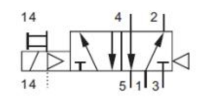
5/2-way valve single solenoid |
|
|
FDF-F14-510 |
Semi in-line |
|||
|
FDF-C10-510 |
Sub-base |
10 |
||
|
FDF-F10-510 |
Semi in-line |
|||
|
FDF-C14-520 |
Sub-base |
14 |
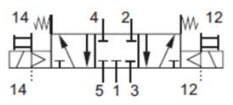
5/2-way valve double solenoid |
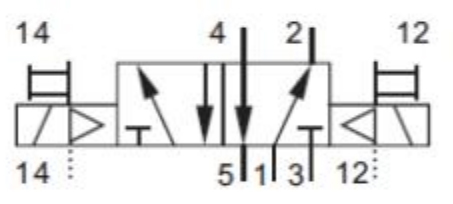 |
|
FDF-F14-520 |
Semi in-line |
|||
|
FDF-C10-520 |
Sub-base |
10 |
||
|
FDF-F10-520 |
Semi in-line |
|||
|
FDF-C14-530 |
Sub-base |
14 |
5/2-way valve mid-position closed |
|
|
FDF-F14-530 |
Semi in-line |
|||
|
FDF-C10-530 |
Sub-base |
10 |
||
|
FDF-F10-530 |
Semi in-line |
|||
|
FDF-C14-533 |
Sub-base |
14 |
5/2-way valve mid-position exhausted |
|
|
FDF-F14-533 |
Semi in-line |
|||
|
FDF-C10-533 |
Sub-base |
10 |
||
|
FDF-F10-533 |
Semi in-line |
|||
|
FDF-C14-534 |
Sub-base |
14 |
5/2-way valve mid-position pressurized |
 |
|
FDF-F14-534 |
Semi in-line |
|||
|
FDF-C10-534 |
Sub-base |
10 |
||
|
FDF-F10-534 |
Semi in-line |
|||
|
FDF-C14-310 |
Sub-base |
14 |
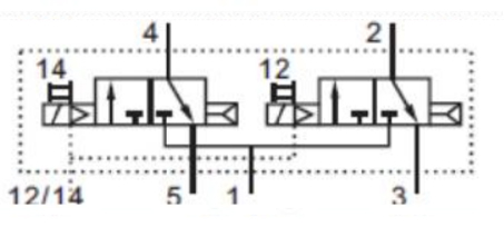
2x 3/2-way valve NC |
 |
|
FDF-F14-310 |
Semi in-line |
|||
|
FDF-C10-310 |
Sub-base |
10 |
||
|
FDF-F10-310 |
Semi in-line |
|||
|
FDF-C14-312 |
Sub-base |
14 |
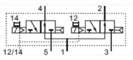
2x 3/2-way valve NO |
 |
|
FDF-F14-312 |
Semi in-line |
|||
|
FDF-C10-312 |
Sub-base |
10 |
||
|
FDF-F10-312 |
Semi in-line |
|||
|
FDF-C14-314 |
Sub-base |
14 |
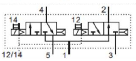
2x 3/2-way valve NC/NO |
 |
|
FDF-F14-314 |
Semi in-line |
|||
|
FDF-C10-314 |
Sub-base |
10 |
||
|
FDF-F10-314 |
Semi in-line |
Valve Dimensions
Valve Parameter
| Specification | Internal Pilot | External Pilot | Flow Rate(L/min) | ||
| Working Pressure(bar) | Pilot Pressure(bar) | Working Pressure(bar) | |||
| 10mm | FDF-510 | 2~8 | 2~8 | 0~8 | 300 |
| FDF-520 | 2~8 | 2~8 | 0~8 | 300 | |
| FDF-530 | 3~8 | 3~8 | 0~8 | 260 | |
| FDF-533 | 3~8 | 3~8 | 0~8 | 260 | |
| FDF-534 | 3~8 | 3~8 | 0~8 | 260 | |
| FDF-310 | 2.5~8 | 2.5~8 | 2~8 | 280 | |
| FDF-312 | 2.5~8 | 2.5~8 | 2~8 | 280 | |
| FDF-314 | 2.5~8 | 2.5~8 | 2~8 | 280 | |
| 14mm | FDF-510 | 2~8 | 2~8 | 0~8 | 560 |
| FDF-520 | 2~8 | 2~8 | 0~8 | 560 | |
| FDF-530 | 3~8 | 3~8 | 0~8 | 500 | |
| FDF-533 | 3~8 | 3~8 | 0~8 | 500 | |
| FDF-534 | 3~8 | 3~8 | 0~8 | 600 | |
| FDF-310 | 2.5~8 | 2.5~8 | 2~8 | 600 | |
| FDF-312 | 2.5~8 | 2.5~8 | 2~8 | 500 | |
| FDF-314 | 2.5~8 | 2.5~8 | 2~8 | 500 | |
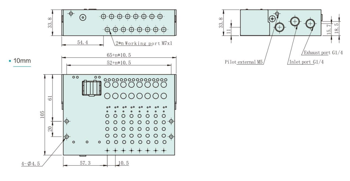
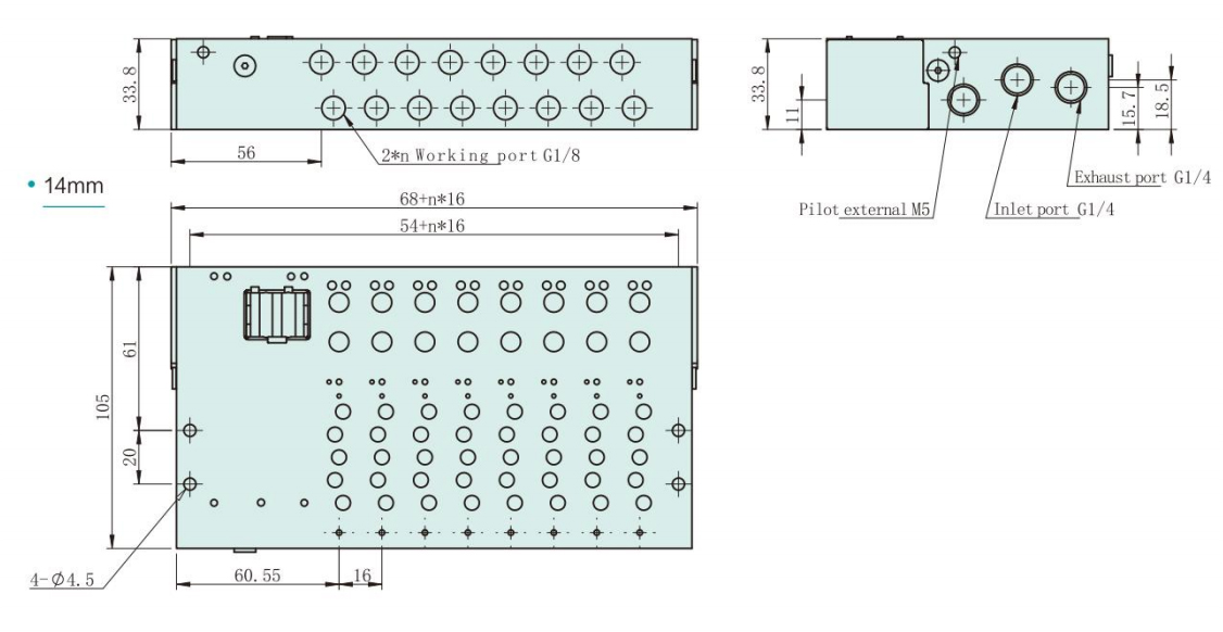
FDM Manifold Assembly
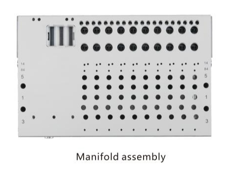
● There are 2 options for manifold: 10mm and 14mm
● Same manifold is used for sub-base and semi in-line valve
● PCB board has been integrated into the manifold
Order code
|
Order code |
Valve Width |
Position Number |
Order code |
Valve Width |
Position Number |
|
FDM-C10-4F |
10 |
4 |
FDM-C14-4F |
14 |
4 |
|
FDM-C10-5F |
10 |
5 |
FDM-C14-5F |
14 |
5 |
|
FDM-C10-6F |
10 |
6 |
FDM-C14-6F |
14 |
6 |
|
FDM-C10-7F |
10 |
7 |
FDM-C14-7F |
14 |
7 |
|
FDM-C10-8F |
10 |
8 |
FDM-C14-8F |
14 |
8 |
|
FDM-C10-9F |
10 |
9 |
FDM-C14-9F |
14 |
9 |
|
FDM-C10-10F |
10 |
10 |
FDM-C14-10F |
14 |
10 |
|
FDM-C10-12F |
10 |
12 |
FDM-C14-12F |
14 |
12 |
|
FDM-C10-16F |
10 |
16 |
FDM-C14-16F |
14 |
16 |
|
FDM-C10-20F |
10 |
20 |
FDM-C14-20F |
14 |
20 |
|
FDM-C10-24F |
10 |
24 |
FDM-C14-24F |
14 |
24 |
Overall Dimension
Additional Accessories
| Cable for Multi-pin Plug | Item | Order Code |
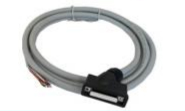 |
Communication(DB25female-scatter)2.5M | S1WA25-K-2.5 |
| Communication(DB25female-scatter)5M | S1WA25-K-5 | |
| Cable for lo-Link | Item | Order Code |
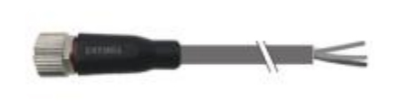 |
Communication(M12female-scatter) outlet straight 2M |
M12-5FS-2115-2M |
| Communication(M12female-scatter) outlet straight 4M |
M12-5FS-2115-4M | |
| Bus Connection Cable | Item | Order Code |
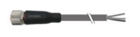 |
Power supply 2M | M12-4FS-2104-2M |
| Power supply 4M | M12-4FS-2104-4M | |
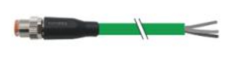 |
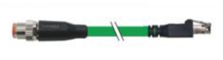
Communication (M12male-scatter)2M | M12D-4MS.P-5544-2M |
| Communication (M12male-scatter)4M | M12D-4MS.P-5544-4M | |
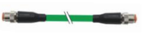 |
Communication(M12male-M12male)2M | M12D-4MS/M12D-4MS.P-5544-2M |
| Communication(M12male-M12male)4M | M12D-4MS/M12D-4MS.P-5544-4M | |
 |
Communication (M12male-RJ45)2M | M12D-4MS/RJ45Y.P-5544-2M |
| Communication(M12male-RJ45)4M | M12D-4MS/RJ45Y.P-5544-4M |
Other lengths of cable are available
| Fitting | Item | Order Code | Fitting | Item | Order Code |
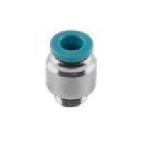 |
G1/8-4 | POC4-G01 | 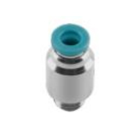 |
M5-4 | POC4-M5C |
| G1/8-6 | POC6-G01 | M5-6 | POC6-M5C | ||
| G1/8-8 | POC8-G01 | M7-4 | POC4-M7C | ||
| G1/4-8 | POC8-G02 | M7-6 | POC6-M7C | ||
| Blanking Plug | Item | Order Code | Silencer | Item | OrderCode |
 |
M5 | TTY-GDTM5 | 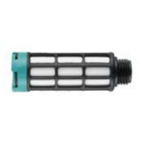 |
Silencer | PSU-A-8 |
| M7 | TTY-GDTM7 | ||||
| G1/8 | TTY-GDT1/8 | 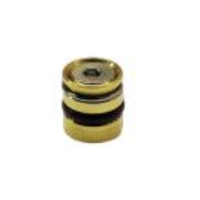 |
Separator for pressure zones |
JEL-FD-FQDT | |
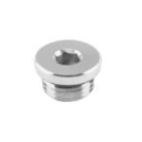
| G1/4 | IBP-G02 | ||||
| Pilot Switching Screw | Item | Order Code | Blanking Plate | Item | Order Code |
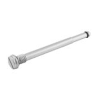 |
Pilot switching screw |
JEL-FD-QHLD |  |
10MM | FDF-C10-B |
| 14MM | FDF-C14-B |
No 1.Xingjia Road, Pneumatic industrial park, Xikou,Ningbo, Zhejiang Zip code 315502
+86-574-88869818
+86-574-88869826
+86-574-88869817
+86-574-88869816
+86-574-88869833
royshan@jelpc.com

Copyright Ningbo Jiaerling Pneumatic Machinery Co.,Ltd.. All Rights Reserved. 
China Proportional Valves Manufacturers
 简体中文
简体中文 English
 日本語
日本語 한국어
한국어 Deutsch